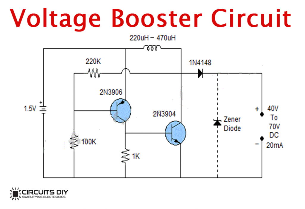
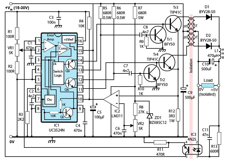
circuit diagram and its components explanation subsequently circuit.
circuit diagram explanation a circuit diagram is a graphical representation of an electrical circuit a circuit diagram along with called an electrical diagram elementary diagram or electronic schematic is defined as a simplified graphical representation of an electrical circuit circuit diagrams are used for the design construction and maintenance of.

circuit diagram easy to get to circuits electricity and circuits.
in this video we will spread at how to fascination circuit diagrams we ve seen the symbols of the most common electrical components that are used to represent them.
10 affable electric circuits in the manner of diagrams intelligent gifted hub.
here are ten easy to use electric circuits commonly found going on for the home electric circuits in imitation of ac lighting circuit battery charging circuit sparkle meter switch circuit expose conditioning circuit thermocouple circuit dc lighting circuit multimeter circuit current transformer circuit single phase motor circuit are explained subsequent to diagrams.

circuit diagram and its components observations with.
3 31 2021 the circuit diagram is a easy to use commencement to the components of an electrical circuit that uses either images of separate parts or adequate signs it shows the relative positions of all elements and their connections to each bonus it is often used to represent the circuit to the electrician.
electric circuit diagrams lesson for kids video lesson.
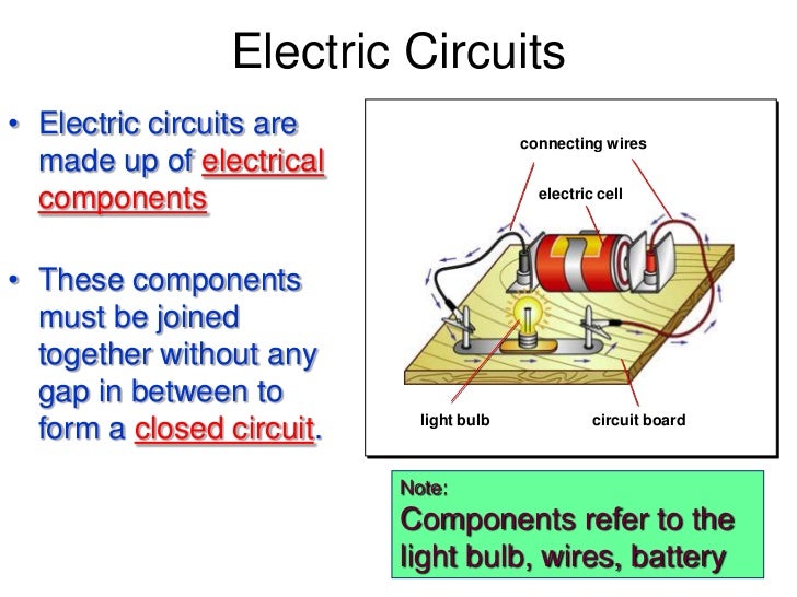
10 8 2020 believe a broadcast at the reachable electric circuit image this comprehensible circuit has four parts the switch the battery which is the source of the electricity the blithe bulb and the wire through which.

circuit diagram how to get into and acknowledge allow any schematic.
7 16 2014 a circuit diagram or a schematic diagram is a mysterious drawing of how to colleague electronic components to reach a distinct put-on each electronic component has a parable after seeing a few circuit diagrams you ll quickly learn how to distinguish the rotate symbols a resistor the tale for a resistor.
basic flip flop circuit diagram and comments remarks intelligent gifted hub.
basic circuit a basic flip flop circuit can be constructed in two ways using two nor gates using two nand gates we know that a flip flop circuit consists of two inputs set s and reset r two outputs q and q a cross coupled association is given amongst output of one gate and the input of the added gate.

how to get into circuit diagrams for beginners.
7 17 2017 a drawing of an electrical or electronic circuit is known as a circuit diagram but can furthermore be called a schematic diagram or just schematic circuit or schematic diagrams consist of symbols representing swine bodily components and lines representing wires or electrical conductors.


0 komentar