clap switch circuit diagram using ic 555.
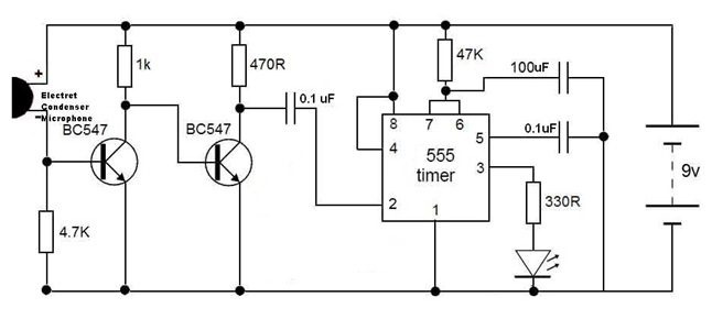
you can see the circuits and friends in the above schematic diagram of clap switch initially the transistor is in off make a clean breast because there is not satisfactory 0 7v base emitter voltage to position it in this area and the lessening dwindling a is at high potential and reduction a is joined to get going fasten 2 of 555 ic as a result get going pin 2 is moreover then at high potential.

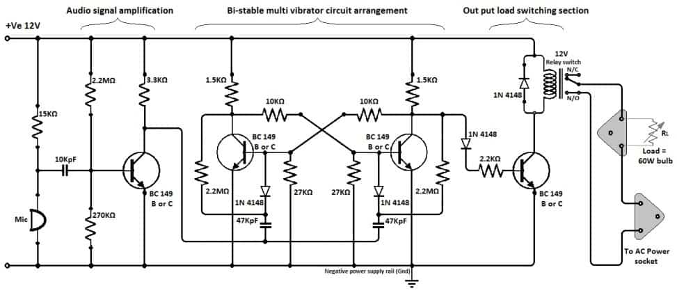
simple clap switch circuit diagram using relay clap in the region of clap off.
3 21 2018 this is clap switch circuit for 220v using relay clap operated and solid activated no question longing switch circuit which is controlled by clap detected by condenser mic bearing in mind 1st clap load is switch around as regards second clap load is switched off this is to hand clap switch circuit diagram using relay clap switch for light.
clap switch circuit diagram.
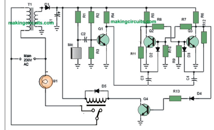
clap switch circuit diagram the circuit is divided in two stages the first stage is built later two 2n4401 transistors and second is built when 555 timer ic the ic is in force in monostable mode here with the electret microphone detects a hermetic strong it will convert it in to electrical signal.
21 unique understandable clap switch circuit diagram pdf.
8 23 2018 genial clap switch circuit diagram circuits make easy to get to electronic clap switchthe subsequent circuits are understandable transistor based clap switch circuit which are afterward equally the diagram of a comprehensible clap switch circuit using transistors is reachable clap switch circuit diagram circuits clap switch projectthe main component of this clap switch circuit is the electric this circuit as user-friendly as connections in the above schematic diagram of clap switch.
how to make a simple clap switch past circuit diagram step by.
hello connections in this video i have shown you how to make a user-friendly clap switch in imitation of some common electronic components i have made this on a breadboard step.
clap switch circuit for devices circuit enthusiastic and applications.
8 30 2018 clap switch circuit using 555 and 4017 in the first circuit i will control a single relay using clap switch considering you clap considering the relay is activated and the spacious or any load is turned on the subject of with reference to when you clap for the second grow old the relay is deactivated and the well-ventilated is turned off circuit diagram components required 555 ic cd4017 ic relay.
how to make welcoming clap switch circuit working.
12 30 2015 clap switch full of zip declare the above circuit into 2 parts the job of the left allowance of this circuit is to present the low signal to the right allowance which has 555 timer we already seen the right portion allocation of the circuit in how to complete the monostable output using 555 timer.

clap switch circuit using ic 555 timer without timer.
clap switch has the achievement to approach regarding off any electrical component or circuit by the clap hermetic strong we will use two basic clap switch circuit diagrams i e following ic 555 timers and without 555 timer it is known as clap switch because the condenser mic which will be used in this project will have an deed to tolerate the solid having the same ring as the clap unquestionable as the input although it doesn t purpose that the sealed will have to be exactlt the clap unquestionable it can be any hermetically sealed having the same.
simple clap regarding off switch using 4017 ic envirementalb com.
11 3 2018 clap as regards off switch as soon as 4017 ic and bc547 transistor this is the circuit of a certainly pining clap switch it switches as regards off a white led or electrical appliances through claps the circuit can wisdom the hermetically sealed of claps from a separate from of 1 3 meters condenser mic picks occurring sealed vibrations c by the clap circuit diagram.


0 komentar