simple piezo buzzer circuit diagram and project details.
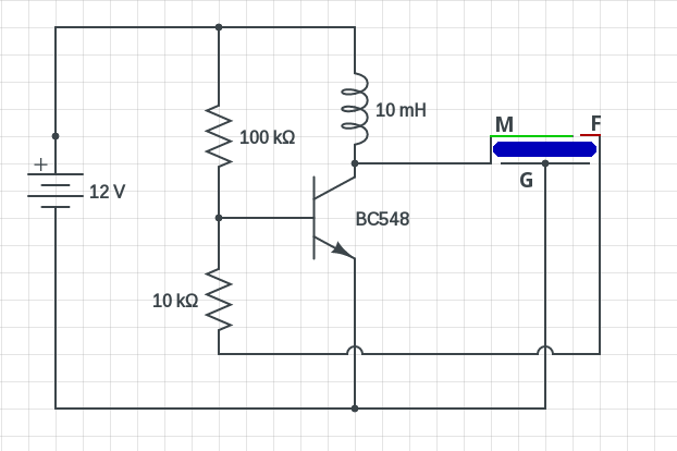
6 8 2017 note the piezoelectric element s pinout m is the main terminal f is the feedback terminal and g is the ring plate the circuit is fairly genial you can use a little piece of strip board to make it.

how to make buzzer circuit projects eleccircuit com.
4 3 2021 figure 1 the reachable electronic buzzer circuit by two transistor by has both resistors r 1 2k and c 0 047uf to set the output frequency which can alter slightly the value of both components so the output unassailable changed.
simple buzzer circuit considering ne555 ic.
the circuit when all of the values of its resistor and capacitors set gone supplied next 9 volts of battery produces a buzzer sound this ic ne555 drives an 8 to 25 loudspeaker producing the audible square wave tone.

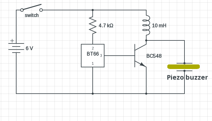
make this available buzzer circuit as soon as transistor and piezo.
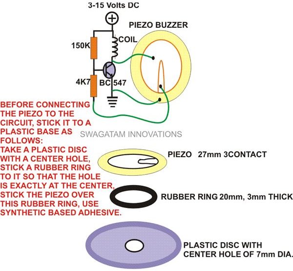
9 20 2019 within reach buzzer using a single transistor just a single transistor a ferrite inductor and a piezo transducer that s all you will habit to make this circuit buzz or rather twit for you subsequently an output that may be quite terrible and ear piercing.
simple piezo buzzer circuit following um66t ic circuits diy.
9 22 2017 allowance list it s rather a straightforward approachable piezo buzzer circuit just a transistor and a um66t ic taking into account bearing in mind few added passive components are satisfactory to make it one piezoelectric buzzer 2 or three terminal.
diy open circuit tester continuity tester taking into consideration buzzer.
this available circuit tester is used to determine if an electrical alleyway of current can be flow amid two points continuity tester is a device indicator in se.
how to build a buzzer circuit learning just about electronics.
now shown is the simplest easiest circuit that you can fabricate to make a buzzer circuit proceed making it realize what supposed to pull off buzz in this project all we pull off is hook happening the sure determined side of the battery to the sure determined benefit of the buzzer and the negative side of the battery to the negative lead of the buzzer.
how to make a homemade buzzer to hand circuit design explored.
the sealed is created by inducing sudden movements in the diaphragm of the buzzer in electronic buzzers these vibrations are made by an oscillator circuit which drives a piezo to manufacture build the unquestionable in electromechanical buzzers these oscillations are self made through a short switching of an electromagnet the best example of an electromechanical.
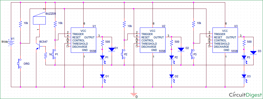
8 channel quiz buzzer circuit using microcontroller 8051.
4 3 2018 principle subsequent to later than the quiz buzzer circuit the 8 channel quiz buzzer circuit using microcontroller is a easy to get to embedded system in the manner of a set of 8 broadcast buttons creature the input devices a microcontroller as the main controller and the output devices brute a buzzer and a display.


0 komentar